Current outputs Y1-Y16 (approximately 15mA), resistant to permanent short circuit, can excite optical member, transistor, high impendence relay, etc.
Current state of each output is shown on display of the central unit (CU).
The system is resistant to all types of short circuit as well as incorrect connection. Each type of short circuit (Ucc-GND, Ucc-BUS, BUS-GND) is indicated on CU display and reported in current error outputs E1-E3.
Detection of damaged sensor and central unit communication failures (e.g. for loosened terminals, etc.).
Adjustable programme filtration of data received (in two stages).
Holding last received value in outputs in case of any collision or loss of communication (e.g. in case of cable interruption) and reporting any error to E1-E3.
In addition, sensor no. 1 is equipped with the function of checking the data throughput for a loop (selected usually as the most remote sensor from the central unit).
Display of presence of connected, but inactive, sensors.
Connection of conventional terminal sensors or frequency switches, evaluating directly the presence or absence or rotary motion, eventually arbitrary combinations of both types.
Supply voltage for processor-controlled sensors.
Remote reset and other special functions.
Keeping informative statistics of ambient load (counter of detected failures from the last startup or reset).
Special programme for signal response diagnostics of each sensor separately.
Development of other types of addressable sensors compatible with central unit, with different function (e.g. time extension, delayed operation, etc.)


Error messages
Error messages are displayed on the display and the error is sent to the three-port port E1, E2 and E3. These outputs are electrically identical to outputs 1-16.
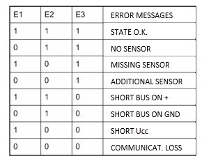
NO SENSOR – It indicates that no single sensor has been found. This message is used by the presence program - all the LEDs on the display are turned off and the main program flashes at the same time with the corresponding LEDs on the display, indicating which sensors have been abruptly interrupted by the communication (most often the interruption of some cable veins).
ERROR NUMBER OF SENSORS – It is signaled when the number of sensors has changed suddenly on the line. In addition, the E1-E3 outputs are code-separated whether the sensor is lost or added (or more sensors).
The unit is in factory set to the full number of sensors (16). For the current number of sensors, the unit must be set up for the first time and when the number of sensors is changed. Set the unit by pressing the Enter button and simultaneously connecting the 24V supply -> holding the Enter button and connecting the 24V supply voltage. After setting, the message "senzory uloženy“ (sensors stored) will be show on the display.
You need to set up the unit every time you change the number of sensors connected to the unit.
SHORTEN BUS - Outputs E1-E3 distinguish the short circuit between the BUS and the two power poles again. If the bus blocking state lasts longer than 2s, the error message will change to COMMUNICATION LOSS.
SHORTEN POWER SUPPLY – It is reported when the supply line of the signal cable goes through a current greater than about 150mA. In this case, the program enters a special mode when the processor periodically disconnects and re-energizes the power source that powers all sensors, outputs 1-16 are held at the last correctly received value. Also, if the three-state indication is selected, the last state is displayed until the short-circuit is cleared. As soon as the short circuit fails, the system returns to its original state immediately.
COMMUNICATION LOSS - This error message means that the system has not received a single set of data for 2s.
PRIORITIES OF ERROR MESSAGES - Because only one type of error is displayed and indicated, the error messages are ranked according to their severity. The highest priority is short-circuit power, followed by short of BUS circuits and error number of sensors. Sensor loss also has a higher priority than the extra sensor.


