Refer to the Data Sheets on the Search in catalogue for technical data
Explanation of terms:
Operating distance (S):
We can bring the metallic object closer to the sensor in axial direction (in the direction of the axis of the sensor) or in radial direction (perpendicular to the axis of the sensor). Operating distance is a distance from the active surface of the sensor, at which the sensor closes or opens the output when moving the metallic object in axial direction. As per standard ČSN EN 60947-5-2 ed.2
Actual operating distance (Sr):
Operating distance of a single proximity sensor, measured at specified temperature, voltage and mounting conditions.
Effective operating distance (Su):
Operating distance of a single proximity sensor, measured at specified conditions.
Distance from sensing area, in which correct functioning of proximity sensor at specified conditions is assured.
Rated operating distance (Sn):
Rated operating distance is an agreed quantity used to designate operating distances. It considers neither manufacturing tolerances, nor changes caused by ambient conditions, such as voltage and temperature.
Reference axis:
Axis perpendicular to sensing area and running through its centre.
Standardized target:
Square-shaped target with thickness of 1 mm made of carbon steel, e.g. Fe 360.
Differential path (H):
Differential path is given as a percentage of actual distance (Sr). It is the difference between the point of closing and the point of opening of the switch. In the below shown figure, the point of closing is marked as (B) and the point of opening is marked as (A). The below figure shows the characteristic of the point of closing and the point of opening of the sensor KS95 C012-U-PNP. This characteristic may be qualitatively applied to other types of sensors.

Sensing curves
Operating distance relation
Repeatability (R):
Is a repeating accuracy of actual operating distance (Sr).
;">Correction factor (K):
Correction factor is a value that should be used to multiply the rated operating distance (Sn) when using screen made of material other than specified for the standardized target.
|
Correction factor (K) |
Material types |
|
1.0 |
Steels |
|
0.9 |
Nickel-chromium alloys |
|
0.5 |
Bronze alloys |
|
0.4 |
Copper, aluminium |
Supply voltage (Ub):
It is the range of voltage, in which the sensor can operate and its reliability is assured.
Rated supply voltage (Ue):
It is supply voltage without tolerances.
Voltage drop (Ud):
Voltage drop is the reduction in voltage, measured on active output of the proximity sensor, at passage of operating current under specified conditions.
Rated operating current (Ie):
It is maximum current that can flow through the load of the sensor.
No-load current (Io):
It is current taken by the sensor itself.
Minimum operating current (Im):
It is minimum current that can flow through the load of the sensor.
Frequency of operating cycles (f):
Frequency of operating cycles is maximum number of closing cycles per second. The operating frequency should be measured according to the following figure.
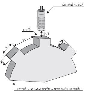
Measurement is performed according to ČSN EN 60947-5-2 ed.2. Targets are attached to the face of teeth of the rotating disc. Gaps in the teeth are 2a so that they can run in front of the sensing area of the proximity sensor at a distance equal to one half of the rated operating distance.
Utilization category:
|
Type of current |
Kategory |
Typical application |
|
Alternating |
AC-12 |
Resistance loads and semiconductor loads with beam splitting |
|
AC-140 |
Small electromagnetic loads with maintaining current 0.2 A; e.g. contactor relays |
|
|
Direct |
DC-12 |
Resistance loads and semiconductor loads with beam splitting |
|
DC-13 |
Electromagnets |
Degree of protection:
As per standard ČSN EN 60529.
Insulated packaging, Class II:
Sensors with insulation class II are packed by embedding process (according to ČSN EN 60947-5-2 ED.2 Annex B), when all components, conductors and ends of integral conductors are packed in insulation embedding mass. The mould, in which the components are placed, is the element of the sensor and thus creates double insulation. The design requirements for class II according to IEC 60536 are hereby met. Sensors with this degree of insulation are marked with the symbol 
Ambient operating temperature:
Ambient operating temperature shall mean temperature of the environment, in which the switch operates. If temperature of the operating environment is in the defined range, a reliable operation of the switch is assured.
Short circuit protection:
Short circuit protection shall mean that the sensor is equipped with an internal overcurrent fuse protecting the sensor output stage by immediate minimization of load current in case of short circuit to load. The limiting current of the internal fuse is higher than the rated operating current (Ie). The sensor starts again operating after the removal of short circuit to load.
Polarity reversal protection:
Polarity reversal protection shall mean that the sensor is resistant to incorrect connection of lead-in wires and thus cannot be damaged.
Cable interruption protection:
This function is met by the switch with connector connection, where the connector counterpart is equipped with built-in LED diode indicating power supply.
Function indicator:
Sensors are usually equipped with LED diode indicating their state.
The following colour indication applies to sensors:
Closing type: orange LED
Opening type, or closing as well as opening: red LED
Element for setting (Sn):
Some types of sensors have the setting element Sn. This is a multispeed trimmer (20 speeds) that is placed in the area of label for types with cable outlet and E, P, H connector and under the connector base for types with K connector. The trimmer is provided with the overspeed protection.
Element for setting (T):
Some types of sensors have the setting element T. This is a multispeed trimmer (20 speeds) that is placed in the area of label for types with cable outlet and E, P, H connector and under the connector base for types with K connector. The trimmer is provided with the overspeed protection.
Electromagnetic interference and its effect on the function of inductive sensors:
In spite of the designers' efforts to prevent an effect of electromagnetic interference on the function of sensors, this phenomenon cannot be fully eliminated. Electromagnetic interference can leak into sensor circuits both through resonance coil and through supply leads. Not even the possibility of interference infiltration through the capacitive relation of the metal housing of the sensor can be eliminated.
In the effort to prevent those effects, filters affecting the operating frequency of the sensor are connected to sensors. It is a matter of common observation that the lower sensing frequency the higher resistance of the sensor to interference.


